MD6290 Rotary Blasthole Drill
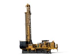


- Technical Specs
- Bit Load
- up to 23 733 kg (up to 52,321 lb)
- Hole Diameter
- 152 - 250 mm (6.0 - 9.875 in)
- Engine
- C15 ACERT - 403 kW (540 hp) at 2,100 rpm
- Multi-Pass Hole Depth (10 m Mast)
- Up to 52.7 m (173 ft)
- Multi-Pass Hole Depth (11 m Mast)
- Up to 32.3 m (106 ft)
- Multi-Pass Hole Depth (8 m Mast)
- Up to 45.1 m (148 ft)
- Single-Pass Hole Depth (10 m Mast)
- Up to 10.1 m (33 ft 2 in)
- Single-Pass Hole Depth (11 m Mast)
- Up to 11.0 m (36 ft)
- Single-Pass Hole Depth (8 m Mast)
- Up to 8.6 m (28 ft 2 in)
- Working Weight
- 120152.0 lb
- Depth multi-pass (10 m/32 ft 9¾ in mast)
- Up to 52.7 m (Up to 173 ft 0 in)
- Depth multi-pass (8 m/26 ft 3 in mast)
- Up to 45.1 m (Up to 148 ft 0 in)
- Depth single-pass (10 m/32 ft 9¾ in mast)
- Up to 10.1 m (Up to 33 ft 2 in)
- Depth single-pass (11 m/36 ft 0 in mast)
- Up to 11.0 m (Up to 36 ft 0 in)
- Depth single-pass (8 m/26 ft 3 in mast)
- Up to 8.6 m (Up to 28 ft 2 in)
- Bit/hole diameter
- 152-250 mm (6-9.875 in)
- Depth multi-pass (10 m/32 ft 9¾ in mast)
- Down to 52.7 m (Down to 173 ft 0 in)
- Altitude
- Up to 4572 m (Up to 15,000 ft)
- Minimum ambient rating (standard)
- -20.0 ° F
- Cold weather package option
- -40.0 ° F
- Maximum ambient rating (standard)
- 125.0 ° F
- Cable sheaves (cylinder) – outside diameter
- 16.0 in
- Cable sheaves (top and bottom) – outside diameter
- 22.0 in
- Cylinder bore – diameter
- 7.0 in
- Cylinder rod – diameter
- 5.0 in
- Head travel (11 m/36 ft 0 in mast)
- 492.0 in
- Head travel (8 m/26 ft 3 in mast)
- 404.0 in
- Number of cylinders
- 1
- Pull-down cylinder stroke (10 m/32 ft 9¾ in mast)
- 232.0 in
- Pull-down cylinder stroke (11 m/36 ft 0 in mast)
- 246.0 in
- Pull-down cylinder stroke (8 m/26 ft 3 in mast)
- 202.0 in
- Sheave guards
- Standard at bottom plate
- Type
- Open-loop, hydraulic (stationary barrel, moving rod)
- Bit load force
- Up to 23 733 kg (Up to 52,321 lb)
- Cable type – 25 mm (1 in)
- DYFORM 8
- Feed rate
- 0-44.8 m/min (0-147 ft/min)
- Head travel (10 m/32 ft 9¾ in mast)
- 464.0 in
- Rated hoist capacity
- Up to 21 364 kg (Up to 47,100 lbf)
- Rated pull-down capacity
- Up to 27 216 kg (Up to 60,000 lbf)
- Retract rate
- 0-46.6 m/min (0-153 ft/min)
- Drive motor
- See Hydraulic System
- Gearbox
- Casting design
- Horsepower capacity
- 182 hp
- Gearing
- Straight spur
- Lubrication
- Oil flooded
- Main thrust bearing
- Taper roller
- Ratio
- 16:1
- Rotation speed
- 0-220 rpm
- Torque
- 0-12 880 N·m (0-9,600 lbf-ft)
- Construction
- ASTM 500 grade B rectangular tubing, welded
- Hose rack
- Sheet steel trough for moving hoses
- Hydraulic lines
- Pressure-rated steel hydraulic tubing
- Main chord size – Front
- 203 mm × 102 mm × 6 mm (8 in × 4 in × 0.25 in)
- Main chord size – Rear
- 102 mm × 102 mm × 13 mm (4 in × 4 in × 0.5 in)
- Pivot and raising area
- Rectangular tubing A frame; reinforced in high-stress areas
- Table hole diameter (diameter deck hole for guide bushing)
- 11.0 in
- Cylinder bore diameter
- 7.0 in
- Cylinder connection pins diameter
- 1.75 in
- Cylinder rod diameter
- 3.5 in
- Cylinder stroke
- 38.0 in
- Lift capacity each cylinder
- 105800.0 lb
- Number of cylinders
- 2
- Construction
- 12 gauge steel welded to formed 12 gauge channel and angle supports
- Door latches
- Heavy-duty latches with lockable handles
- Helper’s seat
- Fixed folding jump seat
- Insulation, floor [closed-cell foam with 3 mm (0.125 in) pyramid vinyl surface]
- 0.375 in
- Insulation, wall and ceiling (thermal)
- 1.0 in
- Left door to work deck
- Swing-type, HD hinge
- Length at floor
- 78.0 in
- Location
- To the right from the mast if facing rear deck from the rear end
- Operator’s seat
- One swivel-type with armrests, headrest and retractable seatbelt
- Right door
- Swing-type, HD hinge
- Sound levels
- 80 dB(A) or less
- Width at floor
- 59.75 in
- Climate Control
- Wall mounted, AC/heating/pressurizing unit
- Floor area
- 32.40 ft2
- Height inside
- 76.50 in
- Number of doors
- 2 with windows (included in above)
- Number of windows
- 10
- Other
- Window wipers and washers
- Type
- Shock-mounted; two-man, integrated FOPS certified
- Windows (tinted safety glass in rubber mounting)
- 0.25 in
- Final drive
- Independent hydrostatic, 2-speed motors
- Gradeability mast down
- 32%
- Overall length (variable with adjustment)
- 200.0 in
- Pad type
- Triple grouser
- Pad width
- 29.5 in
- Rear axle (solid)
- 8.0 in
- Rollers
- Sealed, oil-flooded
- Track adjustment means
- Hydraulic with grease gun
- Track drive disconnect
- Standard (manual)
- Upper track chain support
- Two (2) carrier rollers
- Width over tracks
- 154.0 in
- Brake release
- Automatic
- Brakes
- Spring set, hydraulic release
- Front
- Three-point oscillating type
- Maximum drive horsepower per track
- 196 hp
- Number of rollers on each side
- 10
- Rock guards/chain guides
- Standard full-length guards
- Tram speed – Maximum
- 1.95 mph
- Tram speed – Low speed
- 1.3 mph
- Construction
- Electric welded
- Handrails – Diameter
- 1.9 in
- Handrails – Height
- 48.0 in
- Main rails (ASTM 500 Grade B rectangular tubing heavily cross-braced and reinforced at high-stress areas)
- 203 mm × 406 mm × 13 mm (8 in × 16 in × 0.5 in)
- Toolbox
- Lockable door, below cab side walkway
- Tow hooks
- Welded, two (2) front
- Jacks, mast pivot and deck
- Welded integrally to mainframe
- Machine deck
- Access both sides
- Deck floor material
- Non-skid sheet metal
- Drill deck length
- 104.75 in
- Drill deck width
- 101.5 in
- Hand rails – Diameter
- 1.9 in
- Hand rails – Height
- 48.0 in
- Drill deck area
- 73.8 ft2
- Table height off ground
- 52 in
- Dust deflector
- Natural rubber seal
- Dust deflector – Diameter
- 14.0 in
- Dust deflector – Thickness
- 0.5 in
- Enclosed area
- 45.14 ft2
- Location
- Directly below table bushing
- Material (rubber nylon reinforced)
- 0.25 in
- Split for excess
- Front and rear with 305 mm (12 in) overlap
- Accessory Circuit/Feed Pump (Open-loop) – Maximum flow
- 75.0 gal/min
- Accessory Circuit/Feed Pump (Open-loop) – Pressure rating
- 3335.0 psi
- Accessory Circuit/Feed Pump (Open-loop) – Type
- Axial piston, variable volume
- Fan Circuit Pump – Maximum flow (dual fan)
- 65.0 gal/min
- Fan Circuit Pump – Maximum flow (single fan)
- 57.0 gal/min
- Fan Circuit Pump – Pressure rating
- 3000.0 psi
- Fan Circuit Pump – Type
- Gear
- Fan Drive Motor(s) – Dual fan
- 2
- Fan Drive Motor(s) – Pressure rating (continuous)
- 6000.0 psi
- Fan Drive Motor(s) – Single fan
- 1
- Fan Drive Motor(s) – Type
- Piston
- Filtration (all filters have indicators and bypass) – Case return
- 12 micron absolute
- Filtration (all filters have indicators and bypass) – Charge
- 3 micron, 1 per loop
- Filtration (all filters have indicators and bypass) – Loop
- 12 micron, 2 per loop (optional)
- Filtration (all filters have indicators and bypass) – Main return
- 12 micron absolute
- Left Track/Rotation Pump (Closed-loop) – Maximum flow
- 69.3 gal/min
- Left Track/Rotation Pump (Closed-loop) – Pressure rating
- 5510.0 psi
- Left Track/Rotation Pump (Closed-loop) – Type
- Axial piston, variable volume
- Pump Drive Gearbox – Drive
- Rubber coupler/drive shaft to front of engine
- Pump Drive Gearbox – Type
- 3 pad
- Right Track Pump (Closed-loop) – Maximum flow
- 69.3 gal/min
- Right Track Pump (Closed-loop) – Pressure rating
- 5510.0 psi
- Right Track Pump (Closed-loop) – Type
- Axial piston, variable volume
- Rotation Drive Motor – Pressure rating
- 5000.0 psi
- Rotation Drive Motor – Type
- Axial piston variable volume
- Track Drive Motors (2) – Pressure rating
- 6000.0 psi
- Track Drive Motors (2) – Two-speed
- 107/125 cc
- Track Drive Motors (2) – Type
- Bent axis fixed volume
- Reservoir pressure
- Atmospheric, filtered breather
- Reservoir with sight and temperature gauge
- 170.0 gal
- Type
- Centralized manual (optional auto-lubrication)
- Air cleaner type
- Dry-type with safety element
- Batteries
- Two (2) 8-D
- Engine shut-down system
- Energized to run
- Full load
- 2100.0 RPM
- Jacket water cooling/CAC
- Radiator
- Manufacturer
- Caterpillar
- Muffler (inlet and outlet)
- 5.0 in
- Muffler guard
- 10 gauge for personal protection
- Starting system
- 24V DC
- Turbo and manifold covers
- Blankets and/or exhaust wrap
- Fuel tank
- 365 gal
- Model
- C15 ACERT*
- Optional fuel tank
- 283 gal
- Rated horsepower
- 540 hp
- Note
- *U.S. EPA Tier 3/EU Stage IIIA equivalent
- Air cleaner type
- Dry-type with safety element
- Air cleaner type
- Dry-type with safety element
- Batteries
- Four (4) 8-D
- Batteries
- Four (4) 8-D
- Engine shut-down system
- Energized to run
- Engine shut-down system
- Energized to run
- Full load
- 2100.0 RPM
- Full load
- 2100.0 RPM
- Jacket water cooling/CAC
- Radiator
- Jacket water cooling/CAC
- Radiator
- Manifold covers
- Blankets and/or exhaust wrap
- Manifold covers
- Blankets and/or exhaust wrap
- Manufacturer
- Caterpillar
- Manufacturer
- Caterpillar
- Muffler (inlet and outlet)
- 5.0 in
- Muffler (inlet and outlet)
- 5.0 in
- Muffler guard
- 10 gauge for personal protection
- Muffler guard
- 10 gauge for personal protection
- Optional fuel tank
- 283.0 gal
- Optional fuel tank
- 283.0 gal
- Starting system
- 24V DC
- Starting system
- 24V DC
- Fuel tanks
- 1382 L (365 gal)
1071 L (283 gal) - Model
- C27 ACERT*
- Rated horsepower
- 800 hp
- Note
- *Tier 2 equivalent
- Fuel tanks
- 1382 L (365 gal)
1071 L (283 gal) - Model
- C27 ACERT*
- Rated horsepower
- 875 hp
- Note
- *Tier 2 equivalent
- Air cleaner type
- Dry-type with safety element
- Batteries
- Four (4) 8-D
- Engine shut-down system
- Energized to run
- Fuel tank
- 365.0 gal
- Full load
- 2100.0 RPM
- Jacket water cooling
- Radiator
- Manifold covers
- Blankets and/or exhaust wrap
- Manufacturer
- Cummins
- Model
- QSK-19 (Non-Cert)
- Muffler (inlet and outlet)
- 5.0 in
- Muffler guard
- 10 gauge for personal protection
- Optional fuel tank
- 283.0 gal
- Rated horsepower
- 750.0 hp
- Starting system
- 24V DC
- Air cleaner type
- Dry-type with safety element
- Batteries
- Four (4) 8-D
- Engine shut-down system
- Energized to run
- Fuel tank
- 365.0 gal
- Full load
- 2100.0 RPM
- Jacket water cooling/CAC
- Radiator
- Manifold covers
- Blankets and/or exhaust wrap
- Manufacturer
- Cummins
- Model
- QSK-19 (Tier 2)
- Muffler (inlet and outlet)
- 5.0 in
- Muffler guard
- 10 gauge for personal protection
- Optional fuel tank
- 283.0 gal
- Rated horsepower
- 760.0 hp
- Starting system
- 24V DC
- Filter Indicators
- Filter indicators for engine and compressor intake, filter indicators are standard
- Filter Indicators
- Hydraulic fluid system, indicator lights for interlocks, rotary head rpm gauge and heating systems control are optional
- Location
- Console at front and side cab wall, placed 45° to the deck
- Standard Compressor Controls
- Compressor temperature
- Standard Compressor Controls
- Air pressure gauge
- Standard Compressor Controls
- Air shut-off control (electric) (high air temperature)
- Standard Drilling Controls
- Level indicator (bubble)
- Standard Drilling Controls
- On/off light switch (electric)
- Standard Drilling Controls
- Wiper/washer controls (electric)
- Standard Drilling Controls
- Deck wrench control (electric)
- Standard Drilling Controls
- Dust curtain (electric)
- Standard Drilling Controls
- Dust/water injection (electric)
- Standard Drilling Controls
- Mast lock (electric)
- Standard Drilling Controls
- Carousel indexing control (electric)
- Standard Drilling Controls
- Carousel in/out control (electric)
- Standard Drilling Controls
- Rotation control (electric over hydraulic)
- Standard Drilling Controls
- Mast elevation control (hydraulic)
- Standard Drilling Controls
- Leveling jack controls (hydraulic)
- Standard Drilling Controls
- Drill hourmeter (gauge)
- Standard Drilling Controls
- Carousel indexing (electric)
- Standard Drilling Controls
- Propel controls (electric over hydraulic)
- Standard Drilling Controls
- Pull-down pressure control (pilot hydraulic)
- Standard Drilling Controls
- Pull-down control (electric over hydraulic)
- Standard Drilling Controls
- HOBO/Break-out wrench control (electric)
- Standard Engine Controls
- Fuel level
- Standard Engine Controls
- Coolant temperature/high temperature shut-off
- Standard Engine Controls
- Oil pressure (low pressure shut-off)
- Standard Engine Controls
- Auto shut-down bypass
- Standard Engine Controls
- Voltmeter
- Standard Engine Controls
- Engine hourmeter
- Standard Engine Controls
- Tachometer
- Standard Engine Controls
- Stop button
- Standard Engine Controls
- Start button
- Standard Engine Controls
- Throttle control
- Counterbalance valves
- Internal at each cylinder
- Cylinder bore
- 5.5 in
- Cylinder rod diameter
- 3.0 in
- Cylinder stroke
- 48.0 in
- Cylinder stroke (optional front)
- 60.0 in
- Inner extension boot – Outside diameter
- 8.625 in
- Inner extension boot – Wall
- 0.322 in
- Location
- 2 front; 2 rear
- Pad connection
- Ball and socket
- Lift capacity (each)
- 66500 lbf
- Number
- 4
- Pad diameter
- 24 in
- Bit Sub – Bottom thread
- Depends on bit diameter
- Bit Sub – Diameter
- Depends on pipe diameter
- Bit Sub – Length for 11 m (36 ft 0 in) mast
- 60.0 in
- Bit Sub – Length for 8 m (26 ft 3 in) and 10 m (32 ft 9¾ in) mast
- 30.0 in
- Bit Sub – Table bushing (standard)
- One (1) piece insert
- Bit Sub – Top thread
- Depends on pipe diameter
- Deck Wrench – Impact means
- Stationary jaw
- Deck Wrench – Location
- Drill deck
- Deck Wrench – Wrench plate (T1-Steel)
- 3.0 in
- Deck Wrench – Wrench positioning
- Hydraulic cylinder
- Drill Pipe (optional) – Optional length
- 35.0 ft
- HOBO Break-out Wrench – Power
- Hydraulic Cylinders
- HOBO Break-out Wrench – Support
- Pivot
- HOBO Break-out Wrench – Wrench type
- Patented HOBO (Hydraulically Operated Break-Out)
- Pipe Rack (outside the mast) – Length of drill pipe
- 30.0 ft
- Pipe Rack (outside the mast) – Pipe rack index
- Hydraulic motor through chain drive
- Pipe Rack (outside the mast) – Pipe rack swing
- Hydraulic cylinders (2)
- Pipe Rack (outside the mast) – Size of drill pipe/capacity – 11 m (36 ft 0 in) mast, 2 pipes
- 114 mm to 178 mm (4.5 in to 7 in)
- Winch System (mounted on the mast) – Swivel hook
- Self-closing gate
- Bit Sub (deck bushing) – Table bushing
- Roller bushing or two-piece
- Drill Pipe (optional) – Diameter (customer specification)
- 127 mm-178 mm (5.0 in-7.0 in)
- Drill Pipe (optional) – Length
- 35 ft
- Drill Pipe (optional) – Wall thickness
- 0.75 in
- Drill Pipe (optional) – Threads
- Depends on pipe diameter
- Note
- 4-pod carousel 10 m (32 ft 9¾ in) mast
- Pipe Rack (outside the mast) – Location
- Outside mast
- Pipe Rack (outside the mast) – Length of drill pipe
- 35 ft
- Pipe Rack (outside the mast) – Size of drill pipe/capacity – 10 m (32 ft 9¾ in) mast, 4 pipes
- 127 mm to 178 mm (5.0 in to 7 in)
- Pipe Rack (outside the mast) – Type
- Carousel, with stationary breaker plates
- Top Adapter Sub – Bottom thread
- Depends on pipe diameter
- Top Adapter Sub – Diameter
- Depends on pipe diameter
- Top Adapter Sub – Length
- 28 in
- Top Adapter Sub – Top thread (API Reg.)
- 5.5 in
- Winch System (mounted on the mast) – Cable size
- 0.5 in
- Winch System (mounted on the mast) – Rating
- 8000 lb
- Compressor oil core hose connection (O-ring boss)
- 2.5 in
- Cooler height
- 55.0 in
- Cooler width
- 106.0 in
- Engine radiator – Coolant connections (bottom tank)
- 3.5 in
- Engine radiator – Coolant connections (top tank)
- 2.5 in
- Engine radiator – Top tank
- Sealed top tank, pressure cap, overflow tube and sight glass
- Fan diameter (10 blades)
- 48.0 in
- Fan guard
- Welded
- Fan speed
- 1525.0 RPM
- Hydraulic oil cooler – Air-to-air cooler (O.D.)
- 4.5 in
- Hydraulic oil cooler – Hose connections (O-ring boss)
- 1.625 in
- Hydraulic oil cooler – Standard ambient rating
- 125.0 ° F
- Special Note
- Air-finned, three-core, radiator/aftercooling/hydraulic side-by-side compressor, CAC-stacked
- Cooler height (dual fan)
- 65.0 in
- Cooler width (dual fan)
- 114.0 in
- Engine radiator – Standard ambient rating
- 125.0 ° F
- Engine radiator – Top tank
- Sealed deaeriation tank, pressure cap, overflow tube and sight glass
- Fan guard
- Welded
- Fan speed
- 1700.0 RPM
- Fan – diameter (two fans, 16 blades)
- 46.0 in
- Special Note
- Air-finned, four-core, radiator/hydraulic side-by-side compressor, CAC–stacked
- Cooler height (single fan)
- 61.0 in
- Cooler width (single fan)
- 101.625 in
- Engine radiator – Standard ambient rating
- 125.0 ° F
- Engine radiator – Top tank
- Sealed deaeriation tank, pressure cap, overflow tube and sight glass
- Fan guard
- Welded
- Fan speed
- 1525.0 RPM
- Fan – diameter (10 blades)
- 48.0 in
- Special Note
- Air-finned, three-core, radiator/hydraulic side-by-side compressor-stacked
- Cooler height (dual fan)
- 65.0 in
- Cooler width (dual fan)
- 114.0 in
- Engine radiator – Standard ambient rating
- 125.0 ° F
- Engine radiator – Top tank
- Sealed deaeriation tank, pressure cap, overflow tube and sight glass
- Fan guard
- Welded
- Fan speed
- 1700.0 RPM
- Fan – diameter (two fans, 16 blades)
- 46.0 in
- Special Note
- Air-finned, four-core, radiator/hydraulic side-by-side compressor, CAC–stacked
- Air cleaner type
- Dry-type with safety element
- Air shut-off
- Hydraulic cylinder – operated from operator’s seat
- Controls
- Automatic with safety shut-down
- Drive
- Direct coupled to engine flywheel
- Oil cooling
- Air-to-oil cooler, thermostatically controlled
- Oil filtration
- 12 micron replaceable element
- Oil separation
- Vertical barrier element, pre-separation in 136 L (36 gal) (T-tank)
- Discharge air flow (sea level)
- 1050 ft3/min
- Maximum operating pressure
- 125.0 psi
- Air cleaner type
- Dry-type with safety element
- Air cleaner type
- Dry type with safety element
- Discharge air flow (sea level)
- 1700 ft3/min
- Maximum operating pressure
- 125 psi
- Discharge air flow (sea level)
- 1250 ft3/min
- Maximum operating pressure
- 125 psi
- Air cleaner type
- Dry-type with safety element
- Discharge air flow (sea level)
- 38 m3/min (1,350 ft3/min)
- Discharge air flow (sea level)
- 43 m3/min (1,500 ft3/min)
- Discharge air flow (sea level)
- 33 m3/min (1,150 ft3/min)
38 m3/min (1,350 ft3/min)
43 m3/min (1,500 ft3/min) - Maximum operating pressure
- 350 psi